1 Configuration
This PCB can be used in different ways and different configurations. There are a lot of solder-jumpers (some open, some bridged by default) to customize it for your needs.
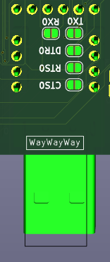
2 Serial connection
RX/TX are on pins PE0/PE1, CTS/RTS are on pins PB4/PB5, all 4 are at their respective ports pins. DTR is connected to Reset block directly.
Together they are on Serial connector on top edge for connecting any external Serial source (default).

Solder-jumpers there enable connection to CH340G USB-Serial convertor.
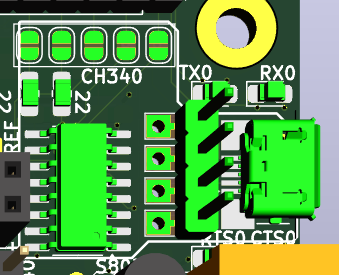
Another set of Solder-jumpers is under CP2102 module and allowe use of that module.
CH340G and CP2102 cannot be used together, or with external Serial (signals <strong>will</strong> conflict).
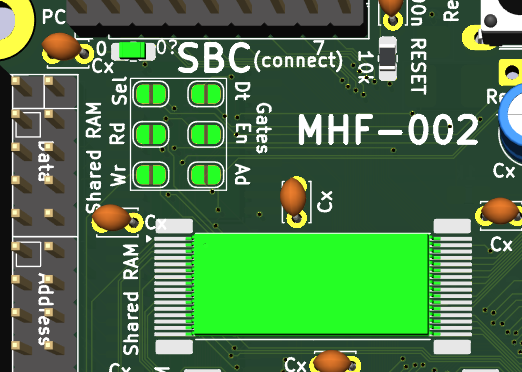
3 SBC config
To use Shared RAM in SBC configuration is needed access to its signals (otherwise managed by GLUE) and maybe to its gates to SystemBus too - simply solder all jumpers in this part and use the new scheme
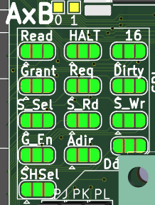
4 AxB SystemBus connection - Graphic Card
Graphic Card configuration is the final goal - this PCB would serve as Input/output for retrocomputer - SystemBus is connected to other PCB, where is retrocomputer and its GLUE is managing Shared RAM and some more signals.
There may be 2 such cards in system (one for VGA/RCA where screen takes 90% of time, other for SD card, PS/2 and Serial, where some transmission needs be uninterrupted by screen). One card will be named A and other will be named B and GLUE will talk to each separately.
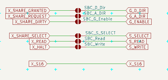
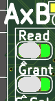
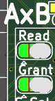
To became Card A solder left part of each of 10 jumpers, to became card B solder right part. (And in both cases unsolder SBC configuration.)
 This is communication from MCU to GLUE.
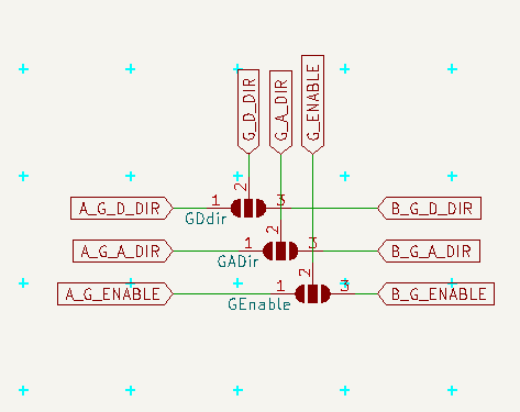 Here is communication from GLUE to gates
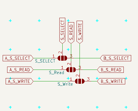 and here communication from GLUE to Shared RAM
Notice, that in order to read/write shared RAM the MCU need ask GLUE to set related signals (and GLUE will do it only if the Shared RAM is owned by MCU)
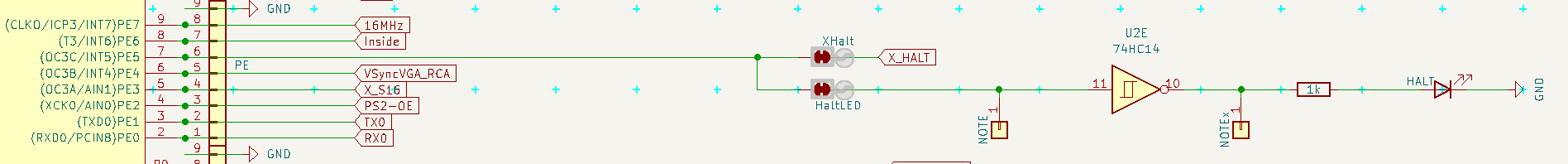
5 HALT + LED
For proper boot of retrocomputer may be needed to fill its RAM with the "ROM" part before it is started.
To do so the HALT should be pulled DOWN (it is active low) and hold there until is all ready.
If this PCB is supposed to do that, it would be good to solder pulldown resistor (and not pullup), after boot actively hold down the line and after setting the RAM (open gates via GLUE, manipulate A0..A16 and D0..D7 and set write signal via GLUE) hold it UP.
If this PCB is suppose to do that, but does not want to doo it, solder pullup resistor (and not pulldown), cut the XHalt jumper and use HALT LED for anything else (like SYSTEM_LED, but beware, it is also active low)
If this PCB is not suppose to do that (the other (AxB) card should do it), do not solder any pull* resistor, cut the XHalt and use LED as you want.
On SBC configuration this line is used to to write to Shared RAM, so do not solder pull* resistors, do not cut XHalt, but you may cut out the HaltLed or leave it to indicate writes to Shared RAM.
Also you may cut the HaltLed and solder any output to this inverted LED or use the invertor for anything else.

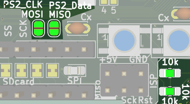
6 PS/2 Direct access + Inside
If you want read the PS/2 direct and process it, solder the 2 jumpers near SPI/SD card (and change the two marked resistors to 1 kΩ)
Also you may want to cut the Inside jumper, as it is probabelly of no use in such scenario.
It also interfere with SPI, which needs address in SW.
7 SD Card
SD Card may be cut off SPI and managed separatelly via its header, but it is probabelly of no use
8 RCA source 40 x 80
This pinhead selects source of graphic data for RCA - the pins are 40,signal,80 and the center (signal) should be connected to one of the sides - 40 selects the UART1 output (and classical driver with 40 characters per line), but I want to test sending there data in similar way as for VGA, so the 80 selects output from VGA module (which may or may not be able to provide 80 characters per line). Now I recomend to use 40.