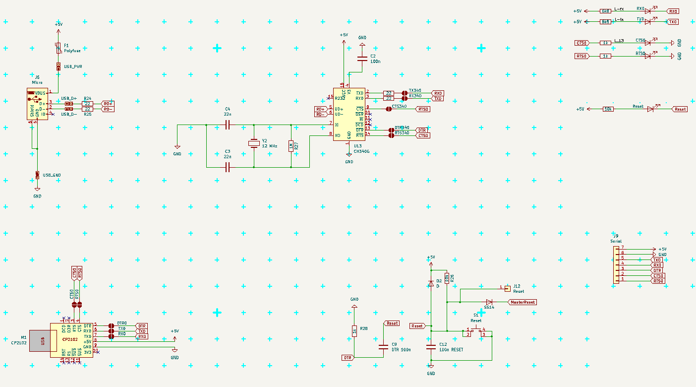
1 serial-usb
https://hackaday.io/project/204418-mhf-002-mega-home-forth/log/244709-serial-usb
1.1 Common
All marks are from MCU signal side of view. (RX is input, TX output, CTS is input, RTS is output, DTR is input).
Default Serial uses USART0 (RX0/TX0 - PE0/PE1 pins) and RTS/CTS (PB5/PB4 pins) and DTR connected to Reset.
There are 3 possible sources for Serial Communication
- Serial pinhead - always conected to MCU, need all signals to be attached
- CH340G with micro USB from Arduino Mega Pro - need to solder connect (RTS/CTS does not work with usual drivers)
- CP2102 module with USB A - need to solder connect
There can be two modes of communication
- full with RTS/CTS flow controll - recomended - protect agains buffer overflow, when PC transmits more data (like a file, or Copy-Paste larger block)
- /gsimply RX/TX like on Arduino, buffer may overflow, cannot paste longer lines
For RTS/CTS the pins must be connected and driver must use it.
Connect RX to TX on of the other part communicating (USB-Serial module, PC, other Arduino ...).
(And TX to RX; CTS to RTS; RTS to CTS; DTR to DTR.) Typical crossing of lines.
The Serial pinhead is already connected to MCU.
CTS is "Clear To Send" and is INPUT, when is low, MCU can send data over TX, when it is high MCU should not send anything
RTS is "Ready To Send", (in new era it is RTR "Ready To Receive") and is OUTPUT, when is low, the other side can send us data, if it is hight, the other side should stop sending
If buffer is too full, set RTS to HIGH until the buffer is empty again.
(It is critical to good communication, as PC have gigabytes of memory, large buffers and fast communication, while ATmega is realitively slow, have small buffer and processing data may take some time. So we need temporaly stop PC from sending more, until we can receive it.)
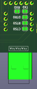
1.2 Serial pinhead
It is "easier" Serial connection as it is just pinhead. It contains all the signals and what is there connected is up to user.
There are LEDs for RX, TX, RTS, CTS near micro USB connector, so communication should be visible. RTS and CTS LEDs are active when the signals are HIGH, which means the direction is BLOCKED. (So use of red LEDs make good sense here.)
DTR is near Reset buton, and does not have LED, the Reset LED indicate any Reset

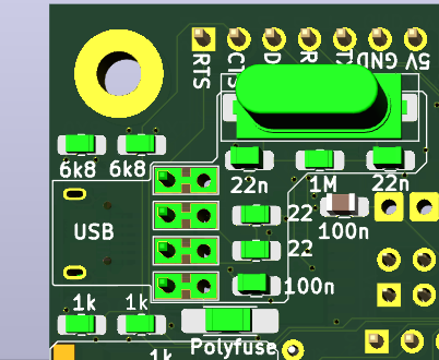
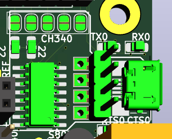
1.3 CH340G
This came from Arduino Mega Pro, where RTS/CTS are not used. If you prefere this behavior, solder only RX, TX and DTR jumpers.
There are problems with drivers for CH340G using RTS/CTS, if it does not work, look for some patch or different driver.
I had problem with the Micro USB connector, that it does not had good and reliable contact and was too easy to damage/rip off. So I added some pinholes for its pins, so I can solder piece of PCB with USB A connector there when problem arise. There are actually two lines of holes, one connected to Micro USB, annother connected to CH340G chip. They are connected on BOTH sides of PCB, so to cut it would need cut on BOTH sides. (I do not think, that it would be needed anyway.)
In case you want use this connector for power only, then populate only the connector and polyfuse (or cut the D+ and D- on both sides of PCB)
1.4 CP2102 module
This module have all signals connected to pins, and have solid USB A connector. To use this module for communication, solder the jumpers on the bottom side of PCB. To use it just as power souce, simply solder the module in.
Notice, that signals should came from max one module at time, so solder/desolder and cut the solderjumpers as needed.
Also notice, that normal Arduino Serial does not use CTS/RTS signals, so in this case is better leave them unconnected.
Also notise, that RTS/CTS flow controll usually need be allowed on the PC side in communication program (Serial terminal and so), Arduino IDE cannot use it at this time.